I’ll be going over some important hardsurface modelling techniques to create a sci-fi weapon scope (and laser!) in Blender. These don’t require you to have HardOps or any other paid addons, so this tutorial should be accessible to everyone. I will go over the whole workflow, from the shape blockout, hardsurface modelling, detail modelling, shading, texturing, lighting and rendering, so get comfortable.
Design
As a first step, I drew a small sketch of a potential model, after being inspired by this railgun by Nicholas Cort. I wanted to go for a trapezoidal profile, and also have some lenses and lasers mounted on the scope, as well as a couple of small controls.
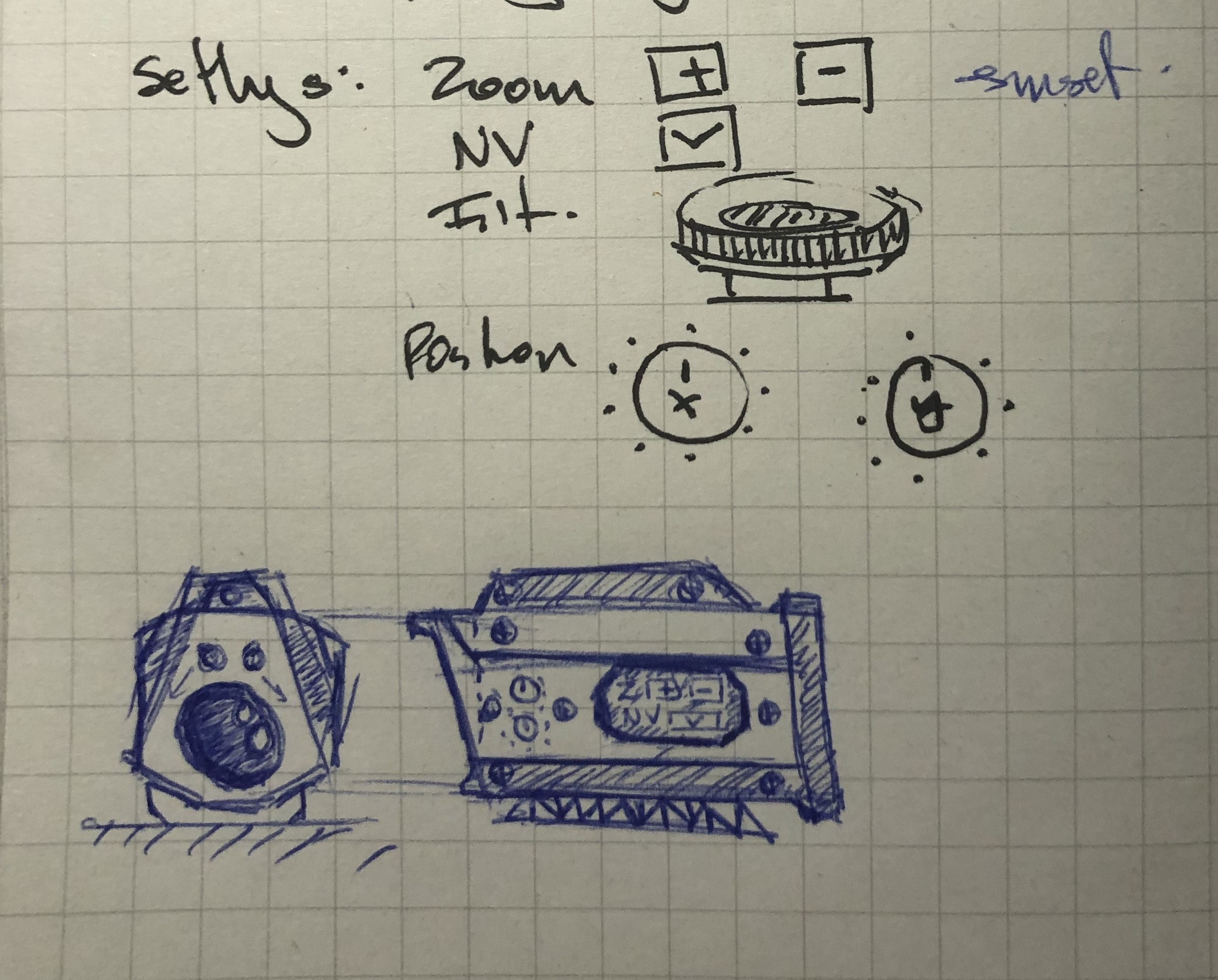
There is a bit to consider here, primarily the functionality of the device. You should be careful to only add parts that make sense, and not randomly. The best artwork tends to tell a coherent story, and that doesn’t come without thought. You must consider not only the aesthetics of the model, but also its functionality. For example, I have several dials and buttons, with specific functions:
- Two upper dials to modulate the X/Y panning of the scope (Say, if you want to look up or right, like an oscilloscope)
- Two power buttons to control the zoom level, allowing one to zoom in and out in discrete steps
- A FLIR toggle button, to enable thermal vision. I don’t think any sights actually have this, but I think it’s a useful detail.
To figure out these functions, think about how the device could be operated, and under what circumstances it might be used. This can always be modified later, but it’s good to have a general idea about how it should look.
Modelling
To understand exactly how to model this scope, please watch my video. I cannot go in depth about the particular extrusions to a depth of D of the face at XYZ … Rather, I’ll give some general hardsurface modelling tips.
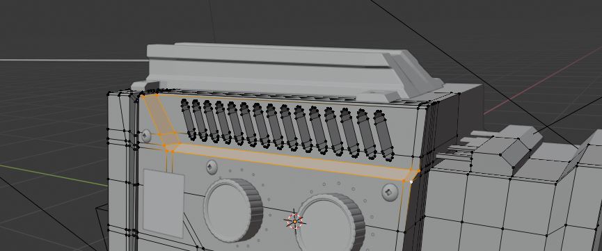
- Make sure your inset faces don’t have sharp edges - that is, at 90 degrees. Create an edge loop the loop, as you can see in the figure below. In this case, it is doubly necessary in order to scale the section down without changing the geometry around it as you need at least two edge loops (highlighted).
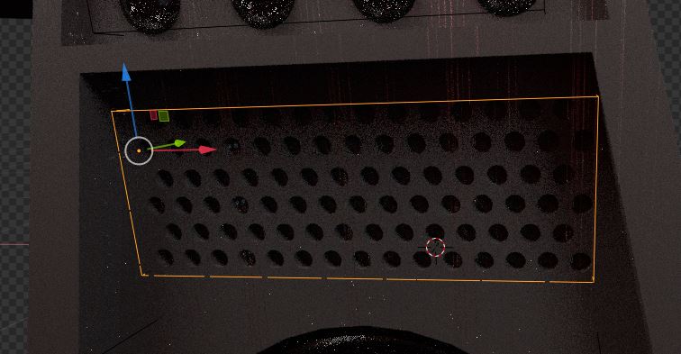
- To make a lot of uniformly spaced protrusions/holes, say, for a vent or speaker, you can use an array modifier (or several) in conjunction with the bool tool to generate a stencil, intersect it with the mesh you want to cut into, and then use CTRL+SHIFT+B > Brush > Difference to make a cut, or CTRL+SHIFT+B > Brush > Union to make a protrusion.
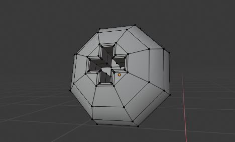
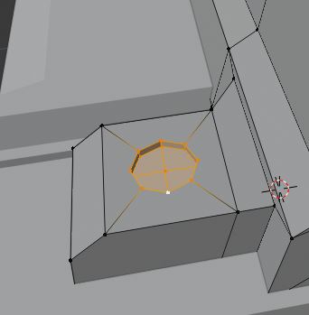
- Screws are easy. The geometry can be seen below. Make an octagon (circle with 8 vertices) and then bridge opposing edges, to make a cross, and extrude it in.
- The looptools RMB in Edit Mode > Loop Tools > Circle or Other functions are incredibly useful if you want to turn a subdivided rectangle into an approximate circle, like I used here - it’s very helpful for divot/inset sections in quad faces:
Shading and Texturing
The shaders I used are here:
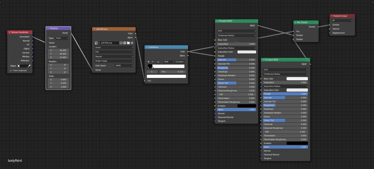
Body Material
Button Material
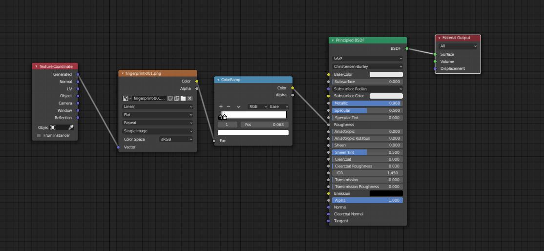
Lens Material
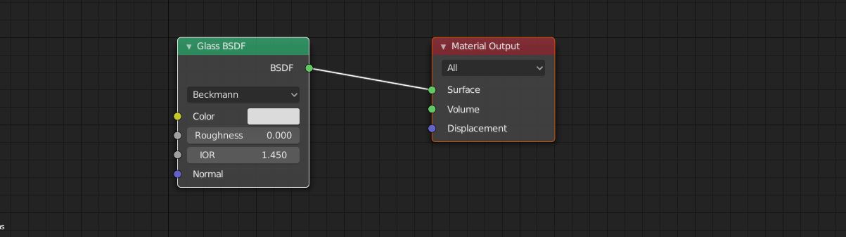
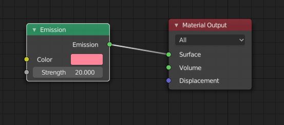
Laser Material
- Some https://www.textures.com/ is a useful source for decal textures.
- For smudges/imperfections, check out this database of contamination textures by Columbia University’s Computer Vision Labs. There is a sizable amount of free textures that can be used here that require no painting on your part.
Details
- I added some decals by using the shrinkwrap modifier. These dials, for example, have markings around them generated by an array of small circles with the “curve” modifier attatched to them, making them arrange themselves into a circle of small circles. Then, a shrinkwrap modifier was applied with a small offset to make it adhere to the body of the scope.
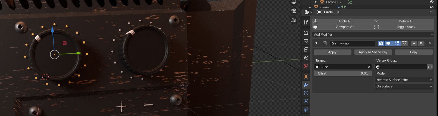
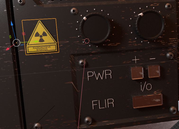
In fact, all of these things - the warning decal, text and dial indicators, are applied with a shrinkwrap modifier:
I may put up a tutorial about making custom decals or sourcing icons for projects later. It’s on my board!
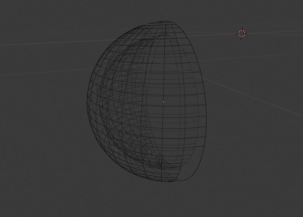
- The lens is not a curved plane. it’s got thickness! That’s a really important point when making believable lenses.
Scene Setup
- Don’t go too crazy with the lighting. I just have a few lights setup in a roughly 3-point structure, and an HDRI from https://hdrihaven.com/, a great place to find HDR lighting.
- HDR lighting is very helpful for photorealistic applications, as adds important reflections that add realism.
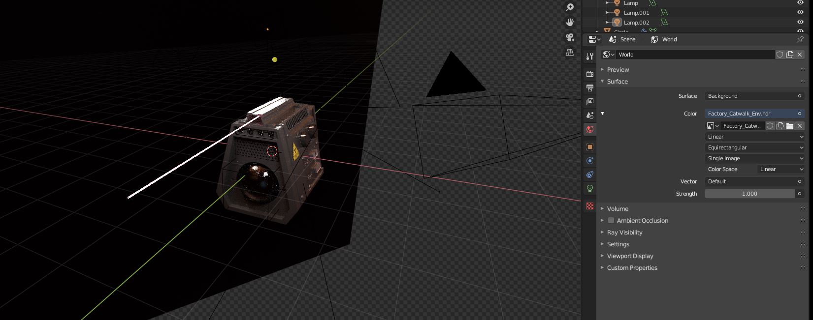
HDR - Factory Sunset
- Some colour grading can go a long way in making your image look better. Remember:
- Lift alters shadows
- Gamma alters midtones
- Gain alters highlights
Here’s my compositing setup:

Conclusion
I hope you found it not too difficult to follow this tutorial. If you had trouble, I suggest you watch the video, as my every step is recorded. If you were able to make a scope, I’d love to see it! Post it down in the comments (if I’ve got that working already). As you can see, it’s not too complex of a process to make an interesting hardsurface model look believable, and you can follow the same sequence of steps every time: Design > Blockout > Detail Modelling > Shading > Lighting > Compositing
If you found this tutorial interesting, there’s a good chance you’ll find my other ones interesting too! Check them out here